Saturday, December 31, 2011

Started Gluing Up PSI Holders, Started Dome Wiring for Mike's Second Dome

Once again I didn't have much time to work on the dome electronics for Mike's second droid, but I did manage to get a little done.

I started with gluing the PSI holder for front PSI, and the DC/DC converter & Display Controller board holder.


Next, I worked on the power distribution system. Where better to start than the on/off switch?


There won't be much activity without batteries, so those got wired up next.


I then added the 9 volt and 5 volt power distribution strips, and the DC/DC converter and Display Controller. The batteries feed into the 9 volt power distribution strip, which feeds the DC/DC converter. The 9 volt board can also power other electronics, such as the PSI circuits I recently assembled. The DC/DC converter sends 5 volts to the 5 volt power distribution strip, which feeds the various JEDI electronic components. I gave a quick test with the rear logics, and all is well.


Still a lot to do.

Friday, December 30, 2011

Second Power Strip, PSI Supports & Dome Bump Work on Mike's Second Dome

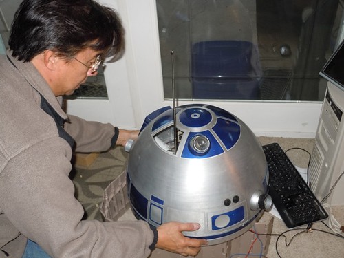
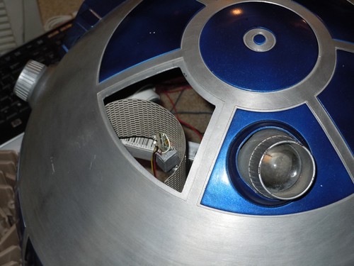
Work on Mike's second droid's dome continues.

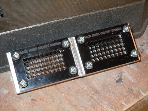
I decided to add support for a second power distribution board. One board will supply 5 volts to Scott Gray's JEDI electronics, and the other will supply 9 volts to any 9 volt circuits that may be added.

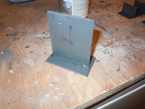
The 9 volt board can serve two purposes. First, the JEDI DC/DC board will get its input from this 9 volt board, and output the 5 volts to the other power distribution board for the rest of the JEDI electronics. Second, it turns out that Mike already had PSI circuits with Scott's JEDI electronics, so he doesn't necessarily need the ones I wired up. But should we choose to use them, we'll have a 9 volt supply for them readily available.

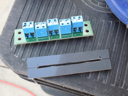
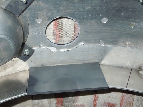
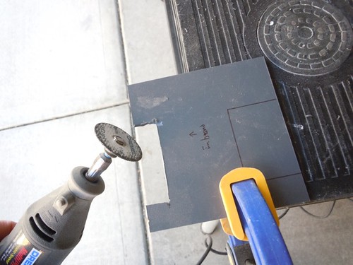
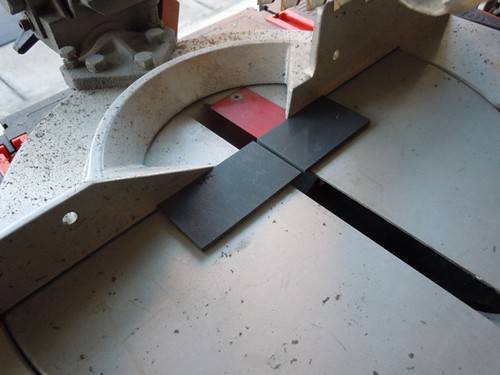
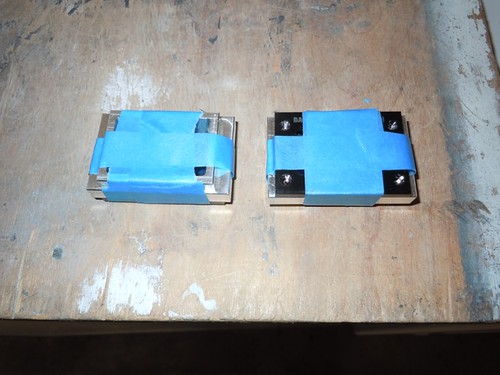
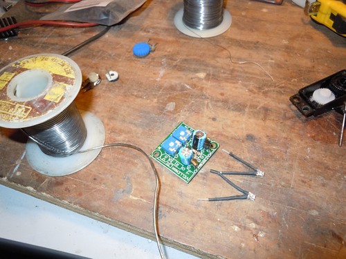
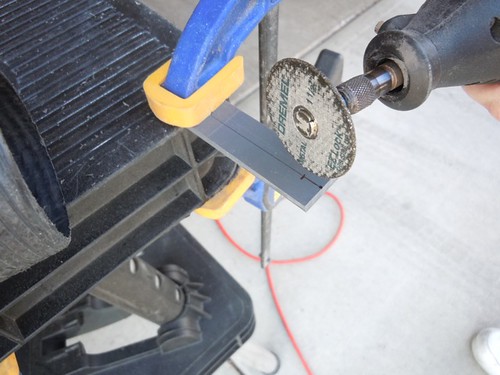
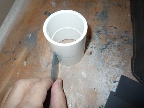
So, I cut another small piece of PVC to host the small power distribution board.


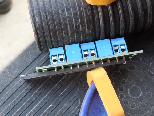
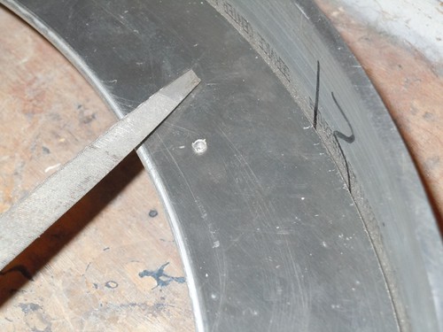
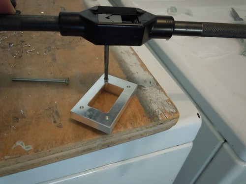
And as was the case yesterday, I needed to cut a groove with the Dremel cutoff wheel to accommodate the pins on the underside of the board.


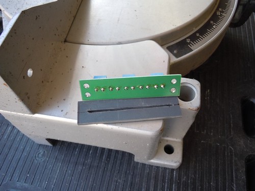
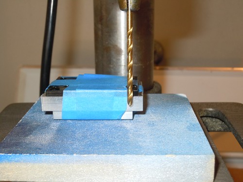
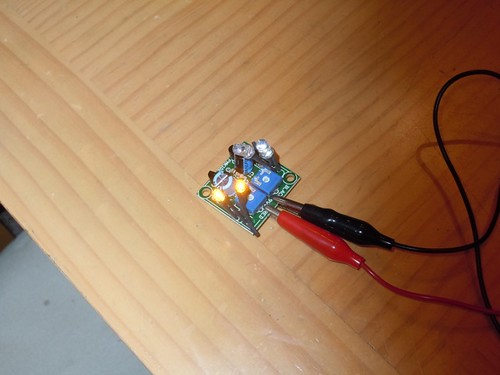
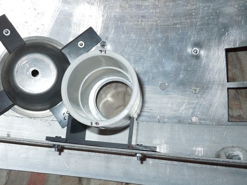
Now the board fits flush on the PVC. The pins are short enough that they do not poke through the bottom.


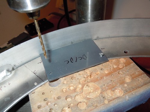
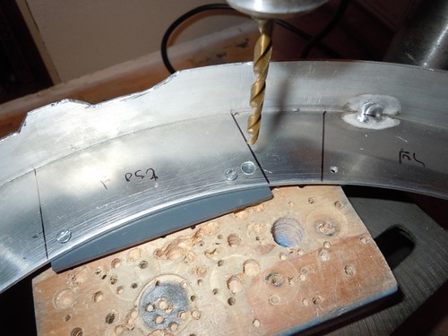
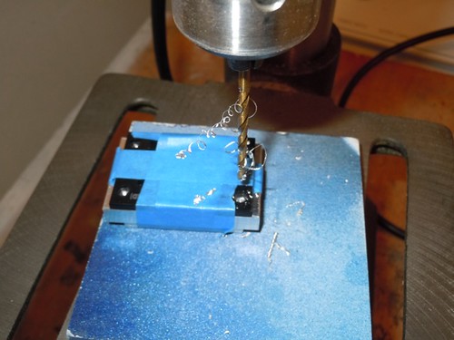
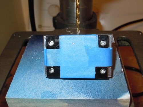
I also needed to drill the dome ring for this additional part, adjacent to the existing power distribution board.


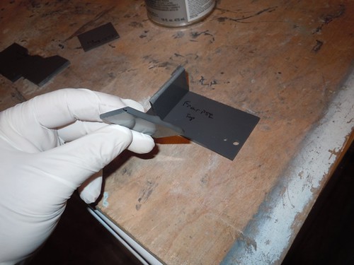
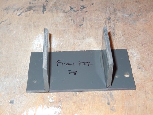
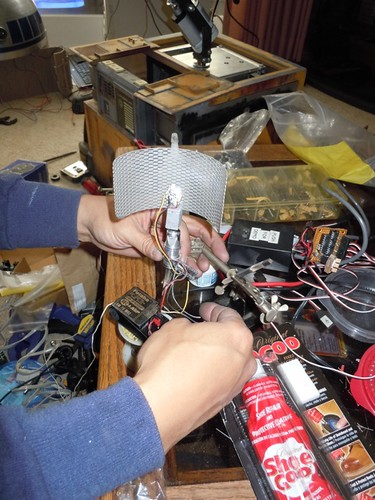
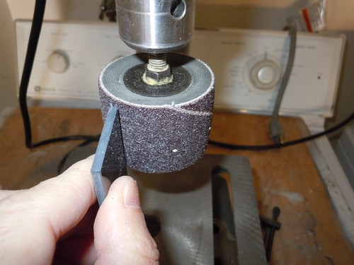
Next, I moved on to the vertical supports for the PSIs. I needed to sand a curve at the top of them, to hug the piece of PVC pipe I'm using to house the PSI circuits. I used a drum sander attachment on the drill press to get this started.


Unfortunately, when it came to fitting everything together, I found that I needed to make an adjustment. The right support needed to be recut, in order to move it closer to the bottom of the pipe in order to avoid the mounting screw on the base plate. I need to sand the curve into this new piece. Poor planning on my part, even though I copied what worked on my second droid!


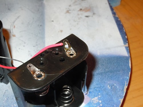
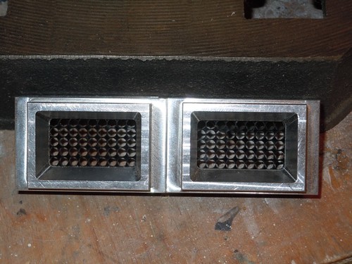
Finally, I returned to the drum sander to sand the square bezel of the dome switches to be circular.


I also needed to sand the threads off the switch, otherwise the switch would not fit through the holes in the dome.


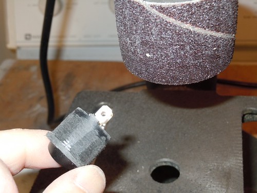
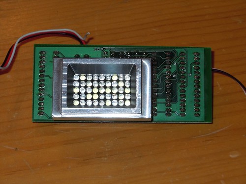
The switches are pretty circular, but I may try to get them even rounder, if my inner perfectionist prevails. My inner pragmatic may tell me to leave them alone.


Later I used acetone to remove the white dots.

I wanted to get a lot further today, but other commitments prevented that. Tomorrow may not be much better.

Thursday, December 29, 2011

Cut More PVC & Drilled Dome Ring for Mike's Second Dome

Today was mostly a replay of September 29, 2010, as I drilled Mike's dome ring for his second droid.

Before getting started on that, I had just a little more PVC to cut, for the vertical supports for the PSIs, and the base plate for power distribution board. I also recut the DC/DC converter base plate to be a little larger.

I started with the small PVC rectangle for the power distribution board.


For the power distribution board, the pins on the back side prevent it from sitting flush on the strip of PVC.


I used the Dremel with the cutoff wheel attachment to cut a groove for these pins.


Now the board sits flush, and the pins are short enough that they won't poke through to touch the aluminum dome ring.


Speaking of the dome ring, it was time to start drilling the holes for all the base plates, having marked their locations yesterday. I used a #33 drill bit for the #4-40 1/2" screws I'm using to mount these base plates.


I also drilled the mounting holes for the battery holders. I have a 4-pack holder and another 2-pack holder for the six C battery cells that I plan to use, to provide 9 volts to the DC/DC converter board.


The front PSI base plate overlaps the front Rockler bearing hole, so I attached the base plate to the underside, and drilled through it where the #10 screw goes. Mike had already drilled the holes in the dome ring for the Rockler bearing.


Once I was done drilling these holes, I filed down the aluminum volcanoes that formed on the underside of the dome ring.


The last item of business was to drill holes on the vertical mounting board for the DC/DC converter board and the display controller. These will share the same piece of PVC, one board will be mounted on each side.


I'm using #6-32 nylon screws to attach the boards to the PVC holder. I drilled three holes total, each diagonally. One of the holes is shared by both boards, the other two are diagonal from it for each board.

Wednesday, December 28, 2011

Winter 2011 CHOC Hospital Visit

Today was R2's quarterly visit to Childrens Hospital Orange County. Last year he wore his New Year's Eve party hat, this year he was a little more subdued.


We visited somewhere between 30 and 40 young patients in their rooms. I always bring goodies to hand out (stickers, action figures, coloring books, etc.). This time one of the employees at the Discovery Science Center was kind enough to have some patches and pins made up for today's visit.


As usual, I can't post pictures of the patients, but the staff certainly enjoyed the visit as much as the kids.


It's always nice to spread some cheer, especially during the holidays.

Marked Mike's Dome Ring for Drilling

Today I had just a few minutes to work on Mike's dome electronics for his second droid.

I laid out the base plates for the various electronics mounting assemblies, and traced their footprints.


Similar to my dome on my second droid, here is the layout for Mike's second droid's dome. I plan to use six C batteries rather than the D cells I use, as I was able to find the proper battery holders at Orvac Electronics in Fullerton, CA. This will help make the dome a bit lighter, yet still provide plenty of run-time on the dome electronics.


I still need to do a little more PVC cutting. I need to build the vertical supports for the PSI holders, and I need to use the Dremel drum sander to work around some of the weld points on the dome ring. I'm also going to recut the DC/DC converter base plate to be a little longer, to help accommodate its dome ring mounting screws.

Tuesday, December 27, 2011

Cut Dome Electronics Housings for Mike's Droid

Today I worked on the PVC housings that will host the dome electronics on Mike's droid #2.

Most of the time was spent measuring, marking and cutting the assembly for the front logics. I recycled an old piece of PVC for the base plate, and then marked where to cut the piece that will hold the logic boards.


Time to bring the Dremel out of retirement and get some cutting done.


I cut a few vertical strips that are used to mount the assembly at the proper angle. Everything is loose-fit for now, but I plan to start gluing it up soon.


I also cut a couple of base plates for the front and rear PSIs. I still need to cut the vertical supports for each.

Monday, December 26, 2011

Drilled and Tapped Mike's Front Logic Surrounds

Today I returned to working on Mike's dome for his droid #2. This time, it was preparing the front logic surrounds for mounting.

These need to be drilled and tapped for a #6-32 screw. I taped down the bezels to the surrounds for use as a template to locate the four mounting holes.


I set the drill press stop to the proper depth, for the #36 (0.1065") drill bit I'm using.


Time to drill!


A short while later I had the four holes drilled for each surround.


Next up, tapping each hole with a #6-32 tap bit. I'm not very good at tapping, but it worked out fine.


A quick test-fit with the bezels on the surrounds, to make sure the alignment looks okay.


So far, so good.


And finally, a test on the front logic circuit itself. Again, things look good.


Hopefully I can start making progress on the housings for the various dome lights shortly.

Thursday, December 22, 2011

Finished Wiring Up Rear PSI for Mike

Today I went by Mike's to finish wiring up the rear PSI for his second dome, and to pick up some dome parts (and the second dome itself), so I can continue work. I also wanted to check out his progress on the life form scanner on his first dome.

I got to work on getting the green LEDs soldered together. These are a pair of NTE part #30038 LEDs with a 100 ohm resistor.


Green works.


The yellow LEDs are of uncertain vintage. Mike had some in a bag, so we just guessed at typical specs (25 milliamps, 5 Vf, 2 in series). Mike suggested using a 100 ohm resistor with a pair of these yellow LEDs, so that's what I went with. One way or another, it works.


In the meantime, Mike was busy at work hooking up the car antenna that will serve as the mast for his droid's life form scanner. This involved dome hacking and other fun construction tasks. It's coming along nicely!


I'll try to get some more work done on the dome electronics for Mike's dome #2 soon.